mini-GNI
Low Cost Giant Cloud Condensation Nuclei Measurement
Fan Modification and Testing
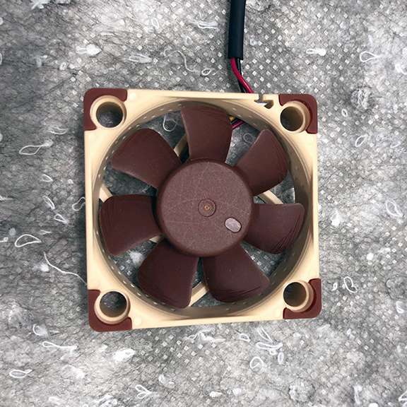
Modifying the NF-A4x10 FLX Premium 40mm computer fan for use as a rotation speed based anemometer is a fast an easy process that can be completed in less than five minutes. Modification of other fan brands is similar, but construction techniques differ between various qualities and brands. The NF-A4x10 FLX has proven to be easy to modify and has a very reproducible calibration curve.
Tools and Materials Required
- (1) NF-A4x10 FLX Computer Fan
- Permanent Marker
- Label maker machine and label tape
- Small flat blade screwdrivers (at least two)
- Small diagonal style wire cutters
- Small pliers
- Loctite 4851 Instant Adhesive
- Socket set
- Pocket or utility knife
Modification Procedure
1. Remove the fan from its packaging, but save the packaging and materials for later storage or mounting of the device.
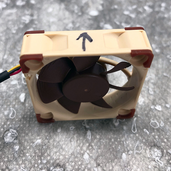
2. Using a permanent marker, put an arrow indicating the direction of airflow on each of the four sides of the fan. The arrow should point from the open side of the fan to the side with the motor mount supports.
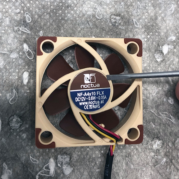
3. Lay the fan with the open side facing down on the bench. Using a knife remove the sticker from the back of the fan. There is a small black magnet in the center of the fan which can be left or removed as it is not essential to the functionality of the fan as an anemometer.
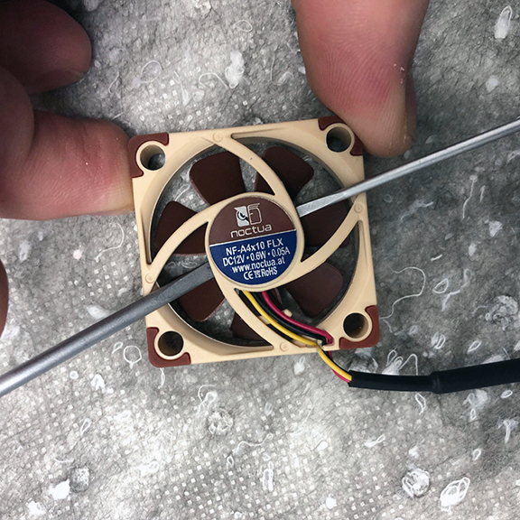
4. Place two small flat blade screwdrivers in between the small PCB and the back of the fan propeller assembly. Gently pry both screwdrivers together while slightly lifting on the fan body to allow the propeller assembly to pop off the mounting inside the fan. This should require very little force and care should be taken to not break any of the motor mount support arms or damage the propeller assembly.
5. The PCB is likely already loose from the removal of the propeller assembly, but if it is not it can be loosened from the light mounting adhesive with a small flat blade screwdriver. Be careful to not damage the PCB.
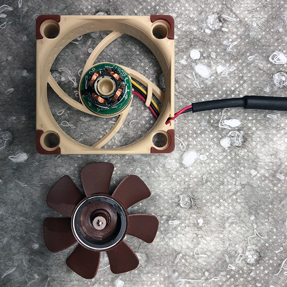
6. Using small diagonal cutters cut the four wires attaching the motor coils (stator) to the PCB.
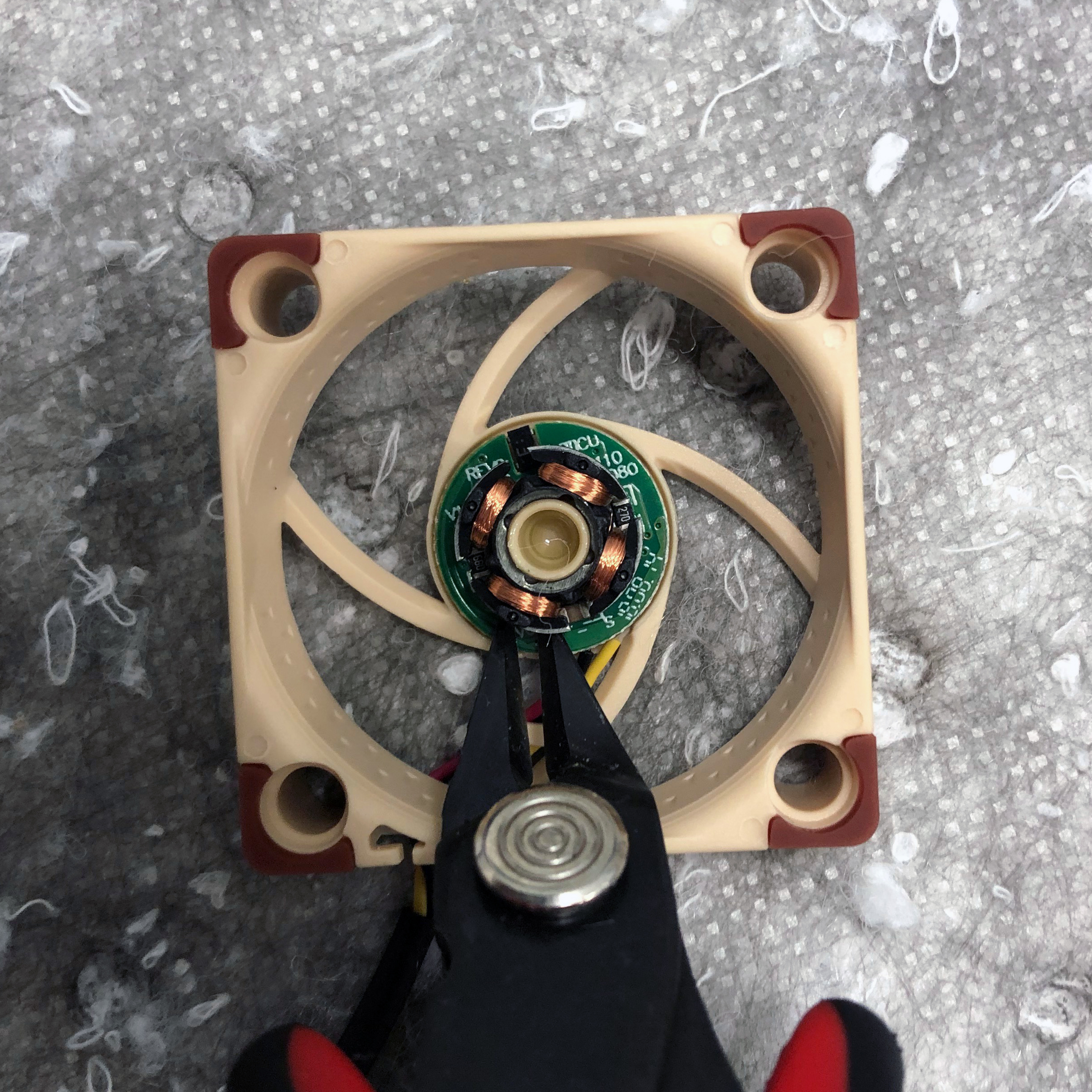
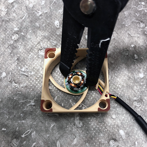
7. Using small pliers twist on the stator to remove it from the bearing boss it is glued around. If the stator does not seem to come off easily, ensure that all of the wires to the PCB have been completely cut.
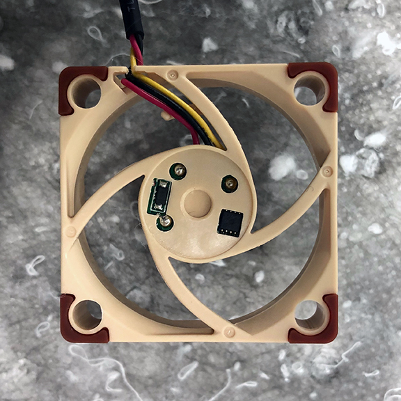
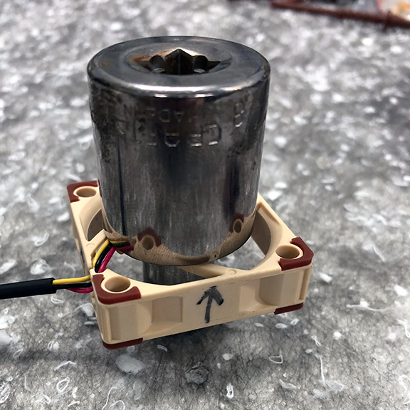
8. Place a 7/16 inch socket on the PCB and flip the fan assembly such that the fan is raised off the work surface and sitting on the socket.
9. Using a small flat blade screwdriver, ensure that the components on the back side of the PCB are properly aligned with the holes that match them in the back of the fan casement.
10. Apply Loctite 4851 instant adhesive into each of the holes in the casement to secure the PCB. Place a larger socket on top of the casement to hold pressure on the joints while they dry. Use a large enough socket that the socket itself does not touch the glued areas.
11. Allow the glue to dry for 5-10 minutes.
12. Press the propeller assembly back onto the bearing boss of the fan casement and ensure that it spins freely. There should be little to no resistance.
13. Using the label maker, create a unique number label for this anemometer to tracking purposes and place it where the old adhesive label was on the back of the motor mounts and supports.
Anemometer Testing
Testing of the anemometer can be performed by simply hooking it up to a completed MiniGNI unit, but this procedure allows testing with basic test equipment independent of any project specific hardware.
Tools and Materials Required
- Power supply
- Oscilloscope and probes
- M/M jumper wires
- Alligator clip leads
-
Insert jumper wires into the connector of the anemometer. Matching colors (Red, Black, Yellow) is recommended for the power, ground, and tachometer connections respectively.
-
Connect a 10k pull-up resistor between the power and tachometer wires.
-
Connect the tachometer wire to an oscilloscope probe.
-
Connect the red power wire and black ground wire to the power supply
-
Connect the oscilloscope probe ground wire to the black ground wire.
-
Apply 3.3 VDC with the power supply.
-
With the oscilloscope set to a long time base, DC coupling, and the appropriate volts/division blow on the fan. You should observe a square wave whose frequency is directly proportional to the fan speed.